Presentation for a physics lesson (grade 11) on the topic: alternating electric current - presentation
1) Alternating electric current. 2) Active resistance. Effective values of current and voltage. 3) Capacitor in the AC circuit. 4) Inductor in an alternating current circuit.
As we know, current (electric) can be alternating and constant. Alternating current is an electric current that periodically changes in magnitude and direction. Currently, alternating electric current is very widely used. It can be obtained using alternating current electric generators using the effect of electromagnetic induction. The figure shows a primitive installation for generating alternating current. The operating principle of the installation is simple. The wire frame rotates in a uniform magnetic field at a constant speed. The ends of the frame are fixed to rings that rotate with it. Springs that act as contacts fit tightly to the rings. A changing magnetic flux will continuously flow through the surface of the frame, but the flux created by the electromagnet will remain constant. In this regard, an induced emf will arise in the frame. Alternating current also refers to current in conventional single- and three-phase networks. In this case, the instantaneous values of current and voltage change according to a harmonic law.
Alternating current in the lighting network of an apartment, used in factories, etc., is nothing more than forced electromagnetic oscillations. These voltage fluctuations are easy to detect using an oscilloscope. (Fig. 4.8) The standard frequency of industrial alternating current is 50 Hz. This means that over the course of 1 s, the current flows 50 times in one direction and 50 times in the opposite direction. A frequency of 50 Hz is accepted for industrial current in many countries around the world. In the USA the accepted frequency is 60 Hz. If the voltage at the ends of the circuit changes according to a harmonic law, then the electric field strength inside the conductors will also change harmoniously. Alternating voltage in the sockets of the lighting network is created by generators at power plants. A wire frame rotating in a constant uniform magnetic field can be considered as the simplest model of an alternating current generator. The flux of magnetic induction Ф, penetrating a wire frame of area S, is proportional to the cosine of the angle a between the normal to the frame and the magnetic induction vector (Fig. 4.9): Ф = BScos a With uniform rotation of the frame, angle a increases in direct proportion to time: a = 2Пnt, where n – rotation frequency. Therefore, the flux of magnetic induction changes harmoniously: Ф = BS cos 2Пnt, Here 2Пn is the number of oscillations of the magnetic flux in 2П s. This is the CYCLIC FREQUENCY of oscillations w=2Пn => Ф = BScoswt
According to the law of electromagnetic induction, the induction emf in the frame is equal to the rate of change of the magnetic induction flux taken with the “-” sign, i.e., the derivative of the magnetic induction flux with respect to time: If an oscillatory circuit is connected to the frame, then the angular speed w of rotation of the frame will determine the frequency w of oscillations of the values EMF, voltage in different parts of the circuit and current strength. If the voltage changes with a cyclic frequency, then the current in the circuit will change with the same frequency. But current fluctuations do not necessarily have to be in phase with voltage fluctuations. Therefore, in the general case, the current strength i at any time (instantaneous value of the current strength) is determined by the formula Here I m is the amplitude of the current strength, i.e., the maximum absolute value of the current strength, and the phase difference (shift) between the fluctuations of the current strength and voltage.
Effective values of current and voltage. Let's move on to a more detailed consideration of the processes that occur in a circuit connected to an alternating voltage source. Current strength in value with resistor. Let the circuit consist of connecting wires and a load with low inductance and high resistance R (Fig. 4.10). This quantity, which we have hitherto called electrical resistance or simply resistance, will now be called active resistance. Resistance R is called active because in the presence of a load that has this resistance, the circuit absorbs energy coming from the generator. This energy turns into internal energy of the conductors; they heat up. We will assume that the voltage at the circuit terminals changes according to a harmonic law: u = U m cos wt
As with direct current, the instantaneous value of the current is directly proportional to the instantaneous value of the voltage. Therefore, to find the instantaneous value of the current, you can apply Ohm's law: In a conductor with active resistance, current fluctuations coincide in phase with voltage fluctuations (Fig. 4.17), and the amplitude of the current is determined by the equality Power in a circuit with a resistor. In an alternating current circuit of industrial frequency (v = 50 Hz), the current and voltage change relatively quickly. Therefore, when current passes through a conductor, such as a light bulb filament, the amount of energy released will also change rapidly over time. But we don’t notice these rapid changes. As a rule, we need to know the average current power in a section of a circuit over a long period of time, including many periods. To do this, it is enough to find the average power over one period. By average power over a period, alternating current is understood as the ratio of the total energy entering the circuit over a period to the period. The power in a DC circuit in a section with resistance R is determined by the formula: P = I 2 R. (4.18)
Over a very short period of time, alternating current can be considered almost constant. Therefore, the instantaneous power in an alternating current circuit in a section having active resistance R is determined by the formula: P = i 2 R. (4.19) Let us find the average power value for the period. To do this, we first transform formula (4.19), substituting expression (4.16) for the current strength into it and using the relation known from mathematics
The average power is equal to the first term in formula (4.20). The value equal to the square root of the average value of the square of the current strength is called the effective value of the alternating current strength. The effective value of the alternating current strength is denoted by I: The effective value of the alternating current strength is equal to the strength of such direct current that the same amount of heat is released in the conductor as with alternating current for the same time. The effective value of alternating voltage is determined similarly to the effective value of current:
Replacing the amplitude values of current and voltage in formula (4.17) with their effective values, we obtain Ohm’s law for a section of an alternating current circuit with a resistor. As with mechanical vibrations, in the case of electrical vibrations we are usually not interested in the values of current, voltage and other quantities in every moment of time. The general characteristics of oscillations are important, such as amplitude, period, frequency, effective values of current and voltage, average power. It is the effective values of current and voltage that are recorded by ammeters and alternating current voltmeters. In addition, effective values are more convenient than instantaneous values also because they directly determine the average value of alternating current power P: P = I 2 R = UI.
Direct current cannot flow through a circuit containing a capacitor. Indeed, in fact, in this case the circuit turns out to be open, since the capacitor plates are separated by a dielectric. Alternating current can flow through a circuit containing a capacitor. This can be verified through simple experiment. Let us have sources of direct and alternating voltages, and the constant voltage at the terminals of the source is equal to the effective value of the alternating voltage. The circuit consists of a capacitor and an incandescent lamp (Fig. 4.13), connected in series. When the constant voltage is turned on (the switch is turned to the left, the circuit is connected to points AA'), the lamp does not light. But when the alternating voltage is turned on (the switch is turned to the right, the circuit is connected to points BB'), the lamp lights up if the capacitance of the capacitor is large enough.
How can alternating current flow through the circuit if it is actually open (charges cannot move between the plates of the capacitor)? The thing is that the capacitor is periodically charged and discharged under the influence of alternating voltage. The current flowing in the circuit when the capacitor is recharged heats the lamp filament. Let us establish how the current strength changes over time in a circuit containing only a capacitor, if the resistance of the wires and plates of the capacitor can be neglected (Fig. 4.14). Voltage on the capacitor The current strength, which is the derivative of the charge with respect to time, is equal to: Therefore, the current fluctuations are ahead in phase of the voltage fluctuations on the capacitor in (Fig. 4.15).
I m = U m C (4.29) The amplitude of the current is equal to: If we introduce the designation: and instead of the amplitudes of the current and voltage, use their effective values, we obtain: The value of X c, the inverse of the product C of the cyclic frequency and the electrical capacitance of the capacitor, is called capacitance . The effective value of the current is related to the effective value of the voltage on the capacitor in the same way as the current and voltage are related according to Ohm's law for a section of a DC circuit. The larger the capacitor capacity, the greater the recharging current. This is easy to detect by the increase in the lamp's incandescence as the capacitor's capacitance increases. While a capacitor's resistance to direct current is infinite, its resistance to alternating current has a finite value X c. As capacity increases, it decreases. It also decreases with increasing frequency. The resistance of the circuit with a capacitor is inversely proportional to the product of the cyclic frequency and the electrical capacity. Current fluctuations are ahead of voltage fluctuations in phase by
The inductance in a circuit affects the strength of the alternating current. This can be proven with a simple experiment. Let's assemble a circuit from a coil with high inductance and an electric incandescent lamp (Fig. 4.16). Using a switch, you can connect this circuit to either a DC voltage source or an AC voltage source. In this case, the direct voltage and the effective value of the alternating voltage must be equal. Experience shows that the lamp glows brighter at constant voltage. Consequently, the effective value of the alternating current in the circuit under consideration is less than the direct current. This difference is explained by the phenomenon of self-induction. If the voltage changes quickly, then the current strength will not have time to reach the values that it would acquire over time at a constant voltage. Consequently, the maximum value of the alternating current (its amplitude) is limited by the inductance of the circuit and will be less, the greater the inductance and the greater the frequency of the applied voltage.
Let us determine the current strength in a circuit containing a coil whose active resistance can be neglected (Fig. 4.17). To do this, we first find the connection between the voltage on the coil and the self-induction emf in it. If the coil resistance is zero, then the electric field strength inside the conductor at any time must be zero. Otherwise, the current strength, according to Ohm's law, would be infinitely large. The field strength being equal to zero is possible because the strength of the vortex electric field generated by the alternating magnetic field at each point is equal in magnitude and opposite in direction to the strength of the Coulomb field created in the conductor by charges located at the terminals of the source and in the wires of the circuit. From the equality = - ki it follows that the specific work of the vortex field (i.e., the self-induction emf е і) is equal in magnitude and opposite in sign to the specific work of the Coulomb field. Considering that the specific work of the Coulomb field is equal to the voltage at the ends of the coil, we can write: e і = -u. When the current strength changes according to the harmonic law: i = I m sint, the self-induction emf is equal to: e і = - L i ' = - Ll m cost. Since u = -е i, the voltage at the ends of the coil turns out to be equal
Consequently, the voltage oscillations on the coil are ahead in phase of the current oscillations by or, which is the same thing, the current oscillations lag in phase from the voltage oscillations by (Fig. 4.18) The amplitude of the current in the coil is equal to: and instead of the amplitudes of the current and voltage, use their effective values, we get: The value XL, equal to the product of the cyclic frequency and inductance, is called inductive reactance. According to formula (4.35), the effective value of the current is related to the effective value of the voltage and the inductive reactance by a relationship similar to Ohm’s law for a direct current circuit. Inductive reactance depends on frequency. Direct current does not “notice” the inductance of the coil at all. At = 0 the inductive reactance is zero (XL = 0). The faster the voltage changes, the greater the self-induction EMF and the smaller the amplitude of the current. An inductor provides resistance to alternating current. This resistance, called inductive resistance, is equal to the product of the cyclic frequency and the inductance. Fluctuations in current strength in a circuit with inductance lag in phase from voltage fluctuations on
2nd semester
ELECTRODYNAMICS
4. Electromagnetic oscillations and waves
LESSON 4/46
Subject. Alternating electric current
Purpose of the lesson: to form in students an idea of alternating current as forced electrical oscillations.
Lesson type: lesson on learning new material.
LESSON PLAN
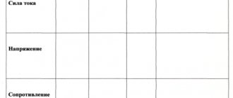
| Knowledge control | 4 min. | 1. Free electromagnetic oscillations in an oscillatory circuit. 2. Energy transformations in an oscillatory circuit. 3. Thomson's formula. |
| Demonstrations | 3 min. | Observation of alternating current oscillograms. |
| Learning new material | 26 min. | 1. Alternating electric current. 2. How to obtain variable EMF. 3. Alternating current generator. |
| Reinforcing the material learned | 12 min. | 1. Qualitative questions. 2. Learning to solve problems. |
LEARNING NEW MATERIAL
Alternating electric current
Ø Alternating current is an electric current that periodically changes in magnitude and direction.
Ø Forced electromagnetic oscillations - undamped oscillations of charge, voltage, current and other physical quantities caused by the emf changing periodically:
A striking example of forced oscillations is alternating current:
How to obtain variable EMF
The source of electrical energy that creates a periodically changing emf is called an alternating current generator.
An alternating current generator can be a wire frame rotating in a uniform magnetic field by induction with a certain constant angular velocity ω.
Magnetic flux through the frame Ф = BScos. The dependence of the angle on time has the form = ωt. Then Ф = BScosωt.
A change in magnetic flux leads to the occurrence of induced emf within the framework. According to the law of electromagnetic induction, the rate of change of magnetic flux DF/Δt from the point of view of mathematics is the derivative of the function Ф(t), therefore
Thus, the frame in question is a source of EMF, which experiences harmonic oscillations in amplitude. If the frame contains N turns of conductor, the amplitude of the EMF increases N times:
To take advantage of the resulting EMF, it is necessary to connect the moving ends of the frame to the fixed contacts of the outer electric circle. You can make a metal ring from each end of the frame slide along its fixed contact (brush). Then the brushes can be considered as the poles of a current source. If you attach a resistor to these poles, the resistance R of which is many times greater than the resistance of the frame and contacts, the voltage across it will be equal to the EMF in the frame u(t) = ωNBSsinωt, and the current strength in the resistor will be:
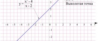
The figure shows a graph of current versus time (Imax = ωNBS).
AC period: frequency:
3. Alternator
The simplest alternating current generator is a metal core with a winding inserted into the slots. The ends of the winding are connected to the rings. The core with the winding rotates in the magnetic field of a stationary permanent magnet or electromagnet. The rotating part of the generator is called the rotor, and the stationary part is called the stator.
The rotor rotation speed can be reduced by using an electromagnet that has several pairs of magnetic poles. The frequency v of the alternating current is related to the rotation frequency of the generator rotor vmax by the relation: v = pvmax, where p is the number of pairs of magnetic poles of the generator.
QUESTIONS FOR STUDENTS DURING PRESENTATION OF NEW MATERIAL
First level
1. Under what conditions do forced electromagnetic oscillations occur in an electrical circuit?
2. What phenomenon is used during the production of electricity in power plants?
3. Why don’t we notice the flickering of light bulbs connected to an AC lighting network?
Second level
1. What energy is converted into electrical energy?
2. What phenomenon is the action of electric current generators based on?
3. Why, during uniform rotation of the frame in a constant magnetic field, not a direct current, but an alternating current is induced in it?
CONSTRUCTION OF LEARNED MATERIAL
). Qualitative questions
1. Is it possible to measure the voltage in an alternating current circuit with a sensitive electrometer?
2. What are used on power plant generators - frames or magnets? What is the reason for this?
). Learning to solve problems
1. The alternating current emf is given by the equation e = 100sin20t. Determine the frequency and period of the current.
2. A rectangular wire frame measuring 20 x 30 cm, having 20 turns of copper wire with a diameter of 1 mm, is located in a uniform magnetic field of induction 0.5 Tesla. The frame is closed to a resistor with a resistance of 6.6 Ohms and begins to rotate at a frequency of 10 rps. Determine the maximum current generated in the frame.
WHAT WE LEARNED IN LESSON
• Alternating current is an electric current that periodically changes in magnitude and direction.
• Forced electromagnetic oscillations - undamped oscillations of charge, voltage, current and other physical quantities caused by EMF changes periodically:
• The source of electrical energy that creates an emf changes periodically is called an alternating current generator.
Homework
1. Sub-1: § 29; Sub-2: § 15.
2. Sat.:
Riv2 No. 9.24; 9.25; 9.26; 9.27.
Riv3 No. 9.31; 9.31; 9.33; 9.34.